
Services
CT Scanning
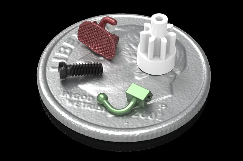
Benefits of industrial CT scanning include:
- Complete internal and external inspection in a single scan
- Non-destructive analysis without cutting apart the component
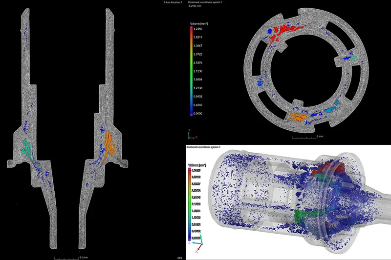
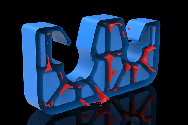
- Detection of internal voids, porosity, cracks, inclusions, and material defects
- Identification of leaks, fatigue damage, and structural failures
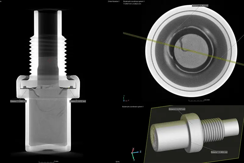
- High-accuracy dimensional inspection of hidden features and internal geometry
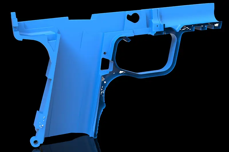
- Reverse engineering of complex parts and assemblies
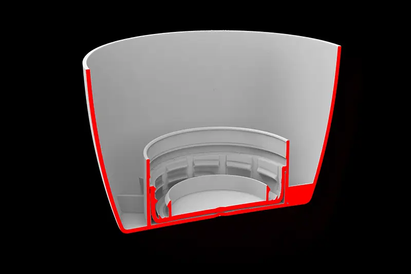
- Wall thickness analysis and assembly verification
- Comparison of scanned data against CAD models for quality inspection
- Ideal for additive manufacturing and highly complex components
- Detailed 3D visualization and reporting for engineering and manufacturing teams
Industrial CT scanning provides a powerful way to validate product quality, investigate failures, improve manufacturing processes, and capture highly detailed internal geometry that would otherwise be impossible to inspect using conventional measurement technologies.
ISO 17025 Certified
Calibrated equipment
Made in North America
Equipment & support
Get a Service Quote
Contact our team to discuss your project and see how 3D scanning can streamline your workflow.
Frequently Asked Questions & Technical Overview
Industrial CT Scanning
Industrial CT scanning is the only practical way to see inside a part without cutting it open. It answers questions that optical scanners and touch probes cannot, but it also comes with its own set of questions about materials, size limits, resolution, and what the data can actually be used for.
The answers below cover what we hear most from engineers, quality teams, and product developers considering CT for internal inspection, defect analysis, or measurement.
01What is industrial CT scanning?
Industrial computed tomography, commonly called industrial CT scanning, is a non-destructive inspection method that uses X-rays to capture the internal and external geometry of an object.
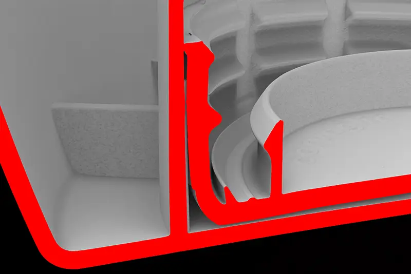
Unlike conventional 3D scanning, which measures visible exterior surfaces, CT scanning reveals features hidden inside a component or assembly. The resulting data can be viewed as individual 2D slices or reconstructed into a complete three-dimensional volume showing internal structures, wall thicknesses, and hidden voids.
02How does an industrial CT scanner work?
The part is positioned between an X-ray source and a digital detector. As the part rotates, the system captures hundreds or thousands of X-ray projection images from different angles.
Reconstruction software combines those images into a three-dimensional volume. The completed dataset lets an engineer virtually slice through the part, examine internal features, separate materials, measure geometry, and look for defects without physically cutting the part open.
03How is industrial CT different from optical or laser 3D scanning?
Optical and laser 3D scanners are limited to line-of-sight surface measurement. Industrial CT penetrates through solid material, so blind channels, enclosed assemblies, wall thicknesses, and internal porosity can be inspected without sectioning or destroying the part. The two methods are often complementary: an optical scanner is faster and simpler for external geometry, while CT is the right tool when the feature of interest is inside.
04How is industrial CT different from a medical CT scan?
The basic principle is similar, but the equipment and applications are different. Medical CT systems are designed to scan people quickly while controlling radiation exposure. Industrial systems are designed for manufactured components and can use longer exposure times, higher X-ray power, different magnification levels, and specialized reconstruction and analysis software.
Industrial CT is used for defect analysis, dimensional measurement, assembly inspection, reverse engineering, and other engineering applications that are not part of a normal medical examination.
05What can industrial CT scanning detect?
Depending on the part and scan setup, industrial CT can reveal:
- Porosity, internal voids, and trapped gas in castings and welds
- Cracks, internal fractures, and foreign-material inclusions
- Incomplete fusion, unfused powder, and keyhole porosity in additively manufactured parts
- Delamination, fiber orientation, and resin-starved areas in composites
- Internal passages, cavities, and wall-thickness variation
- Assembly misalignment, missing components, pinched wires, damaged seals, and broken internal connections
- Material-density variations and dimensional or geometric deviations
The smallest detectable defect depends on scan resolution, material, part size, defect orientation, and the surrounding geometry.
06Is industrial CT scanning non-destructive?
Yes. CT allows a component to be inspected without cutting, disassembling, or otherwise altering it. The X-rays map the internal structure without changing the part’s mechanical integrity, chemistry, or dimensions, which makes it ideal for high-value prototypes, aerospace components, and medical devices that must be returned to service or tested further.
Radiation-sensitive electronics, film, biological materials, and certain specialized products may require additional review before scanning.
07What materials can be CT scanned?
Plastics, polymers, rubbers, silicones, composites, ceramics, electronic components, and light metals such as aluminum, zinc, and magnesium alloys are good candidates for industrial CT.
Dense materials such as steel, titanium, nickel alloys, tungsten, and lead are harder for X-rays to penetrate. They can still be scanned, but part size, wall thickness, required resolution, and available X-ray energy become especially important. A small steel component may be a practical CT application, while a much larger or thicker steel part may require specialized high-energy equipment or a different inspection method.
08What limits a CT scanner’s ability to penetrate a part?
X-ray penetration depends on two factors: material density and part thickness. Dense material absorbs more X-ray energy. If a part is too thick or dense for the system’s tube voltage, the result is X-ray starvation or severe beam-hardening artifacts in the data. Higher-energy systems (225 kV, 450 kV, or linear accelerators) extend what can be scanned, but every system has a practical ceiling.
09Are there size or weight limits for industrial CT scanning?
Yes. The part must fit within the scanner’s usable measurement volume and stay within the equipment’s weight limit.
Size also affects resolution. A smaller part can be positioned closer to the X-ray source and scanned at greater magnification. A larger part requires a wider field of view, which reduces the ability to resolve very small details. For quoting purposes, we need overall dimensions, weight, material, and areas of interest, not just a photograph.
10What is a voxel, and what does CT resolution mean?
A voxel is the three-dimensional equivalent of a pixel. Every voxel in a CT dataset represents a tiny cube of physical space with a grey value corresponding to the material density at that location. Resolution describes the system’s ability to distinguish small features that are close together, and it is often discussed in terms of voxel size. Metrology-grade systems reach voxel sizes in the low micron range on small parts.
Smaller voxels provide finer detail, but voxel size alone does not guarantee that a feature or defect can be seen or measured. Material density, noise, X-ray penetration, movement, reconstruction settings, and image artifacts all affect what is actually visible in the scan.
11Is voxel size the same as measurement accuracy?
No. Voxel size and measurement accuracy are related but not the same thing. A scan can have a small voxel size and show very fine detail while still carrying greater dimensional uncertainty.
Measurement accuracy also depends on equipment calibration, system stability, magnification, surface determination, scan setup, material, and analysis method. If the CT data will be used for dimensional inspection rather than visualization, the required tolerances should be reviewed before scanning begins.
12How accurate is industrial CT scanning?
There is no single accuracy value that applies to every CT scan. Well-configured metrology CT systems can achieve measurement accuracy in the range of ±0.005 mm to ±0.025 mm on suitable parts, but the result always depends on the equipment, part size, material, geometry, magnification, X-ray settings, environmental conditions, reconstruction, and measurement method.
A metrology application should be planned differently from a scan intended only to locate an internal defect. Critical dimensions may also be verified against a calibrated artifact or another measurement method when appropriate. The best starting point is to provide the part drawing, CAD model, and required tolerances so the project can be evaluated properly.
13Can CT scan an assembled product without taking it apart?
In many cases, yes. Scanning a sealed assembly such as a medical inhaler, fuel injector, connector, or electronic device allows a virtual disassembly: engineers can inspect gear mesh, spring compression, contact points, seal seating, gaps, interference, disconnected wires, and missing parts without breaking the housing.
The ability to separate individual components depends heavily on material density. If two adjoining parts absorb X-rays at nearly the same rate, distinguishing the boundary between them can be difficult, and dense metal components can obscure lower-density materials behind them. We review the assembly construction and materials before recommending CT.
14Can industrial CT be used for dimensional inspection and CAD comparison?
Yes. CT data can be aligned to a nominal CAD model and used to evaluate internal and external dimensions, wall thicknesses, feature locations, surface profiles, GD&T, and other geometric characteristics. The software produces a color deviation map showing where the physical part departs from design, on external surfaces and inside hidden geometry alike.
CT is particularly useful when the features being measured cannot be reached with a probe or seen by an optical scanner. Dimensional work requires a suitable scan setup and an understanding of the required tolerances; a scan that is adequate for visual defect detection is not automatically adequate for precision measurement.
15Can CT scanning be used for porosity and defect analysis?
Yes. Industrial CT is widely used to locate and quantify porosity, voids, inclusions, cracks, and other internal conditions. Analysis software can report defect location, individual defect size, total defect volume, defect distribution, distance from a machined surface, porosity within a selected region, and the relationship between defects and critical features.
Acceptance limits must normally come from the customer’s drawing, specification, industry standard, or engineering requirements. CT identifies and measures the condition; it does not determine what is acceptable unless those criteria are provided.
16How does CT scanning help with additive manufacturing?
Metal and polymer 3D-printed parts can suffer from internal keyhole porosity, unfused powder traps, internal stress warping, and rough or incomplete lattice structures, none of which are visible from the outside. CT provides complete non-destructive evaluation of internal cooling channels, density distribution, lattice integrity, and powder removal in complex printed designs.
17Can CT data be used for reverse engineering?
Yes. Industrial CT is especially valuable when a part contains internal passages, enclosed cavities, or other features that cannot be measured with an external 3D scanner.
The CT data can be segmented to isolate the part’s geometry and exported as a polygon mesh. That mesh becomes the reference for building a surface, solid, or parametric CAD model. The CT scan itself is not a finished CAD model; reverse-engineering work is still required to produce clean, editable geometry.
18How long does an industrial CT scan take, and how is the part prepared?
Scan time depends on resolution requirements, part size, and material density. A high-throughput check on a low-density plastic part might take a few minutes, while an ultra-high-resolution metrology scan of a complex metal component can take 30 minutes to over an hour, plus reconstruction and analysis time.
Preparation is minimal because CT is non-contact. Parts generally do not need matting spray or surface treatment. They do need to be mounted securely in low-density foam or a custom fixture so there is zero movement during rotation.
19What deliverables are provided from an industrial CT scan?
Depending on the project, deliverables can include:
- Raw 3D volumetric files (DICOM, VGL) for slice-by-slice visualization
- Surface mesh files (STL, OBJ, PLY) extracted from internal and external boundaries
- Dimensional inspection reports with GD&T results and color deviation maps
- Porosity and inclusion analysis reports with quantitative void-volume data
- High-resolution 2D cross-section images and rotational fly-through videos
The report format is agreed on before scanning so the analysis matches how the data will be used.
20What information do you need to quote an industrial CT scanning project?
Please provide as much of the following as possible:
- Overall part dimensions, weight, and material(s)
- Maximum material or wall thickness
- Photographs from several angles and the quantity of parts
- Features or defects of interest, and the approximate size of the smallest defect that must be detected
- Required dimensional tolerances, if measurements are needed
- A CAD model and engineering drawing, when available
- Whether the part is an assembly and whether it can be disassembled
- Required analysis or report format and completion date
It is also important to explain what problem you are trying to solve. Finding a suspected crack, measuring internal passages, analyzing casting porosity, inspecting an assembly, and creating CAD geometry are different applications and may require different scan setups.
