
Services
Dimensional Inspection
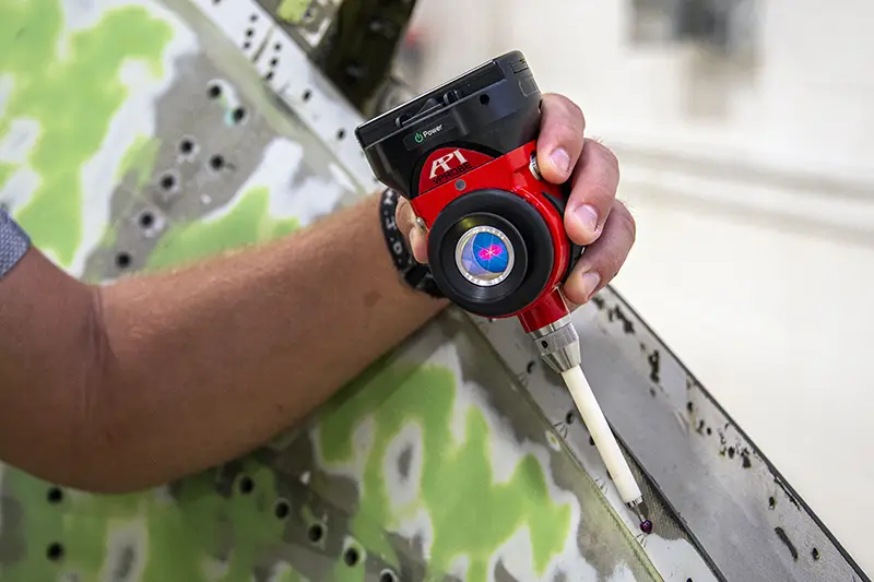
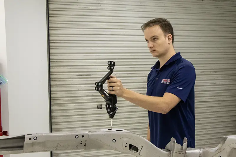
- High-accuracy inspection using multiple metrology technologies
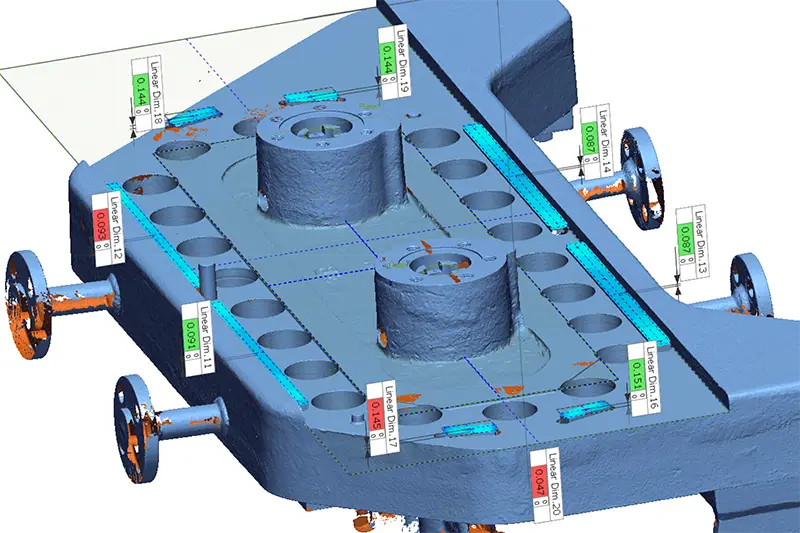
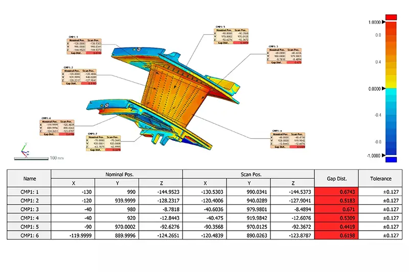
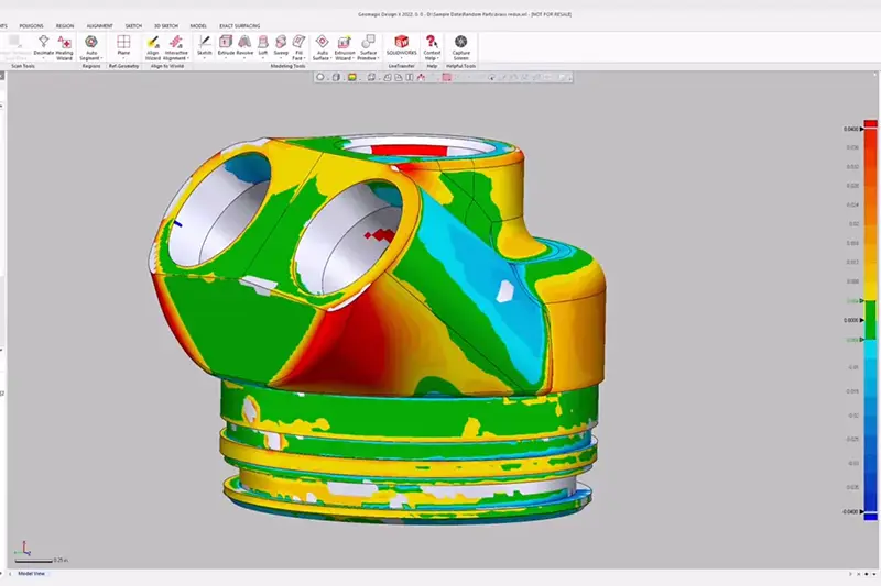
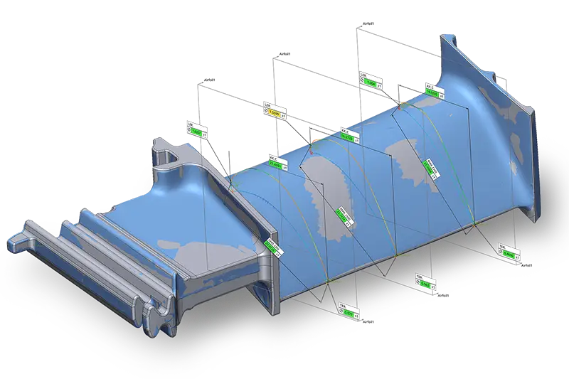
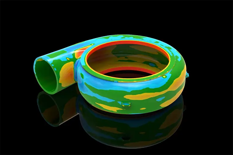
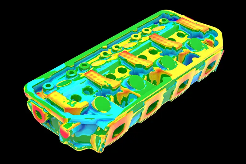
- Detailed color mapping and CAD-to-part deviation analysis
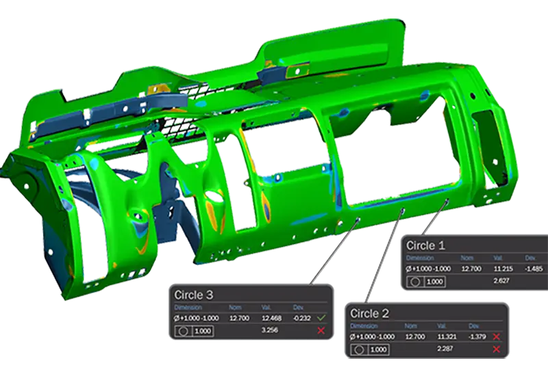
- GD&T inspection and feature-based measurement reporting
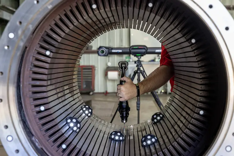
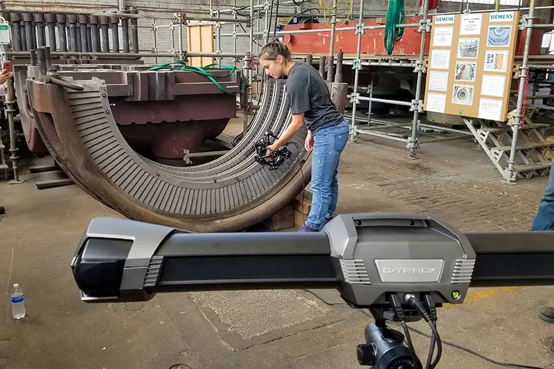
- Large-scale assembly alignment and verification capabilities
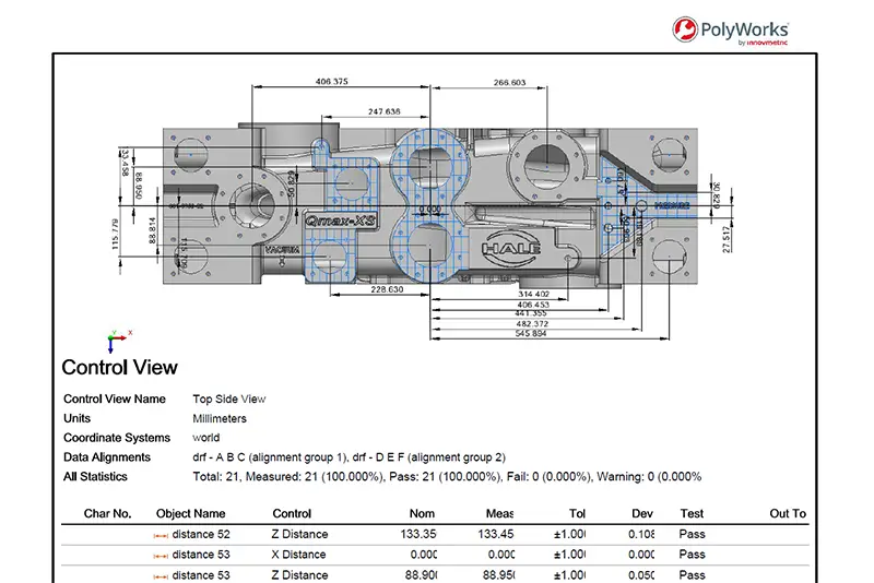
- Comprehensive reports with spreadsheets, charts, tabulated measurements, and engineering documentation
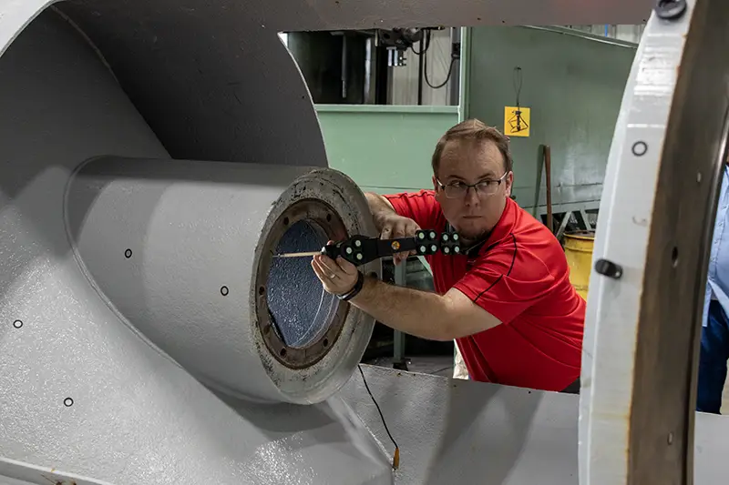
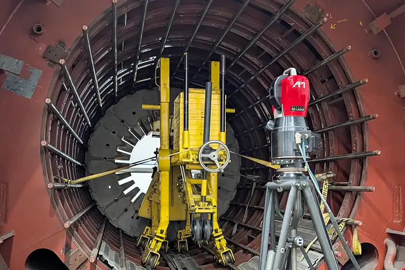
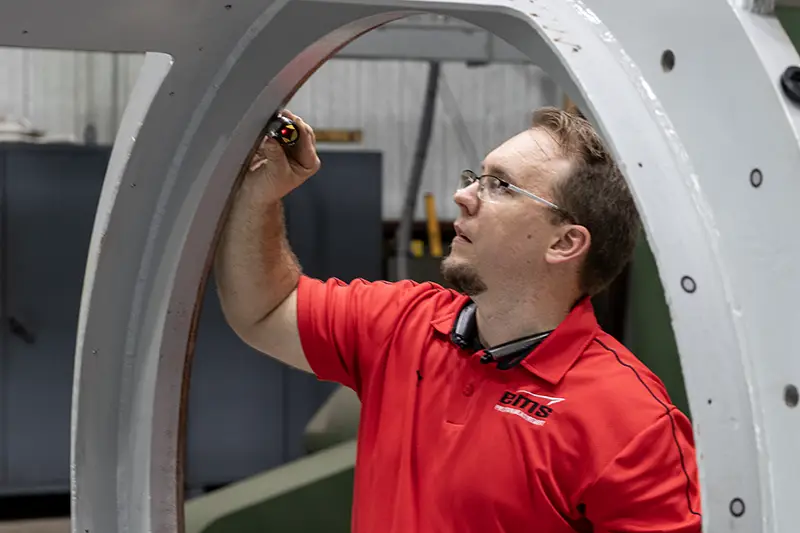
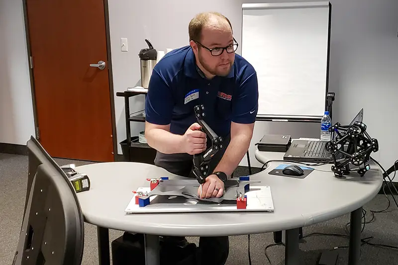
- Portable inspection services performed at customer facilities
- Identification of dimensional problems, wear, distortion, or tolerance failures
- Support for aerospace, automotive, marine, defense, manufacturing, and energy industries
EMS3D dimensional inspection services provide companies with accurate, reliable, and actionable measurement data that can be used to improve manufacturing quality, validate assemblies, reduce production issues, and support engineering and quality assurance workflows.
Shop Floor Inspection Methods
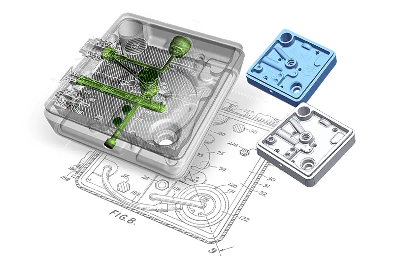
Scan to CAD to Inspect
Get a Service Quote
Contact our team to discuss your project and see how 3D scanning can streamline your workflow.
Frequently Asked Questions & Technical Overview
Dimensional Inspection
Dimensional inspection is where a manufactured part meets its drawing. 3D scanning has changed how that comparison gets done, capturing the whole surface instead of a handful of probe points, but it also raises questions about accuracy, alignment, GD&T, and what the finished report actually tells you.
The answers below cover the questions we hear most from quality managers, manufacturing engineers, and buyers evaluating scan-based inspection for the first time.
01What is dimensional inspection?
Dimensional inspection is the process of measuring a manufactured part and comparing the results to its engineering drawing, CAD model, or other design requirements. The purpose is to determine whether the part was manufactured within its specified tolerances before it enters production, ships to a customer, or goes into an assembly.
Depending on the project, an inspection may include basic dimensions, complex surface profiles, hole locations, concentricity, flatness, parallelism, position, and other geometric requirements.
02How is 3D scanning used for dimensional inspection?
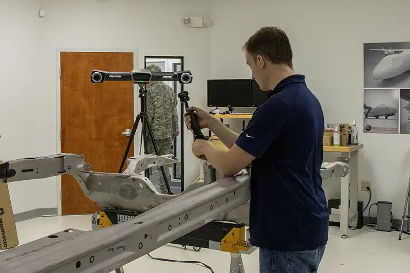
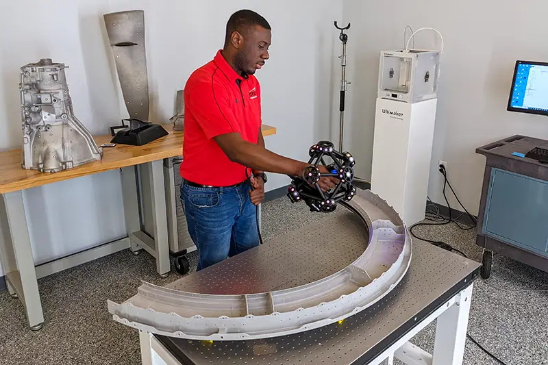
A metrology-grade 3D scanner captures millions of measurements across the visible surfaces of a part in minutes. The scan data is aligned to the nominal CAD model and analyzed with inspection software, which calculates the difference between the manufactured part and the original design.
That lets us inspect individual dimensions and GD&T callouts while also evaluating the overall shape of the part, including freeform surfaces, complex curves, and flush features that are difficult to check any other way.
03How does 3D scanning compare to calipers, micrometers, and CMM probes?
Traditional inspection tools measure individual points or features. They remain useful and are often the right choice for straightforward measurements and very tight feature tolerances. A tactile CMM in particular can reach sub-micron precision on prismatic features, hole diameters, and deep internal features.
A 3D scanner captures a much larger portion of the part’s surface. That gives a more complete picture of the manufactured condition and makes it far easier to spot distortion, warpage, tooling problems, and out-of-tolerance areas that sit between probe touch points. The best method depends on the part, tolerance, material, surface condition, and the information the customer needs. Many projects use both.
04Is 3D scanning accurate enough for dimensional inspection?
Yes, provided the scanner and inspection method are appropriate for the required tolerance. Metrology-grade optical and structured-light scanners typically deliver accuracies in the range of ±0.005 mm to ±0.030 mm depending on the system, field of view, calibration, and environmental control, which is suitable for aerospace, automotive, and medical work.
Real-world accuracy also depends on part size, surface condition, scanning environment, alignment method, and how the inspection is performed. Before quoting a project, we review the drawing and tolerances to make sure the selected equipment can produce meaningful results. A scanner should never be chosen just because it can scan the part; its accuracy has to suit the features being inspected.
05What is a color deviation map?
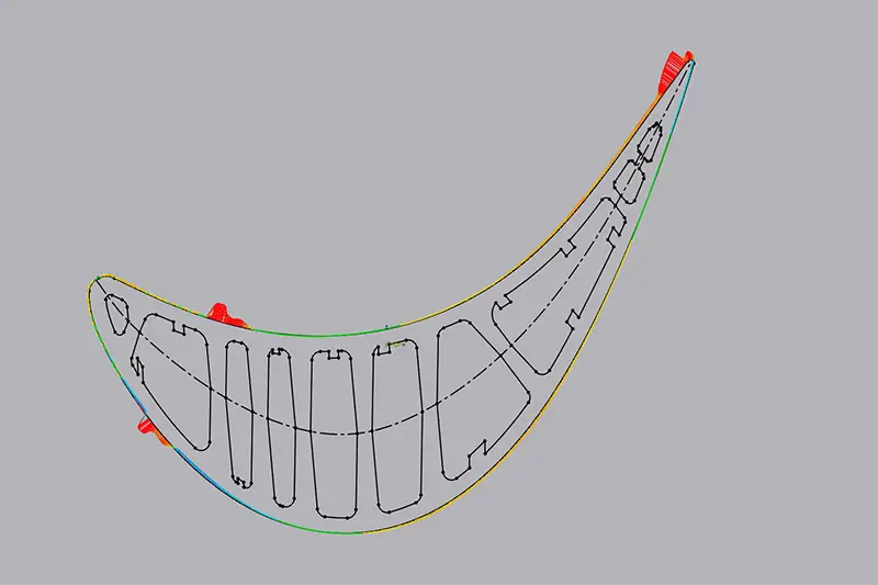
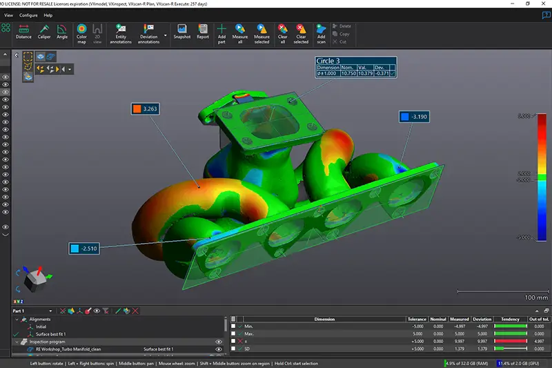
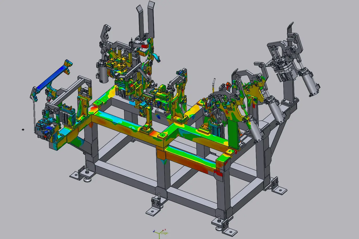
A color deviation map is a visual comparison between the scanned part and the nominal CAD model. The inspection software overlays the scan on the CAD and color-codes the surface: green for areas within the selected tolerance range, warm colors (red and orange) for positive deviation where extra material is present, and cool colors (blue and purple) for negative deviation where material is missing.
Color maps make it easy to see warpage, distortion, high and low areas, incorrect contours, tooling or forming problems, material movement, assembly-fit issues, and patterns that would be hard to recognize from individual measurements. The color scale and tolerance range can be adjusted to match the needs of the inspection.
06Does a green color map mean the entire part passed inspection?
Not necessarily. Green normally means the measured surface falls within the displayed color-map range, but that range may not match every tolerance on the drawing.
A part can appear mostly green and still fail a critical dimension, hole position, flatness requirement, or other GD&T callout. The color map should be reviewed together with the specified dimensions and tolerances, not treated as a stand-alone pass or fail decision.
07What is GD&T, and can 3D scanning evaluate it?
Geometric Dimensioning and Tolerancing is the standardized language of symbols on engineering drawings that defines the allowable variation of geometric features. Modern inspection software can calculate GD&T callouts directly from scan data once datum reference frames are established on the scan mesh.
Depending on the available drawing and CAD data, we can evaluate flatness, straightness, circularity, cylindricity, parallelism, perpendicularity, angularity, position, profile of a line, profile of a surface, and runout. Proper datum setup is critical. The drawing must clearly identify the datum features, tolerance values, and any applicable material-condition modifiers.
08What is alignment, and why does it matter?
Alignment establishes how the scan data is positioned relative to the CAD model, and the method chosen can have a major effect on the results. Common options include datum-based, feature-based, best-fit, reference-point, and localized or constrained alignment.
A best-fit alignment minimizes the overall difference between the scan and the CAD model, but it may not represent how the part is located or assembled in actual use. When datum requirements are provided, a datum-based alignment is generally used so the part is evaluated according to the engineering drawing. The alignment method should always be identified in the inspection report.
09What is the difference between a best-fit alignment and a datum alignment?
A best-fit alignment positions the scan to minimize the overall deviation between the measured part and the CAD model. It is useful for evaluating general surface shape, tooling, castings, molded parts, and parts without clearly defined datums.
A datum alignment uses the datum features identified on the engineering drawing. This simulates how the part is located for inspection or how it functions within an assembly. The two methods can produce noticeably different results, so we select the alignment based on the drawing requirements and the purpose of the inspection.
10Can you perform first article inspection?
Yes. First article inspection verifies that a new or revised manufacturing process, mold, or tooling setup can produce a part that meets every engineering requirement before production begins.
3D scanning speeds up FAI considerably. Instead of hours spent aligning a part on a layout plate or programming hundreds of individual probe touches, the scanner captures the full geometry in minutes and the software generates the dimensional results, GD&T evaluations, surface deviation maps, and cross sections the report needs. The exact report format should be agreed on before the inspection begins, particularly if a customer-specific form or AS9102-style report is required.
11Can you inspect parts without a CAD model?
Yes, but the inspection options will be more limited. If a 2D drawing is available, individual dimensions and GD&T requirements can still be inspected. If no drawing or CAD model exists, we can compare multiple parts to one another, investigate specific features, or use a selected sample as the reference.
A complete surface comparison normally requires a nominal CAD model. If none exists, EMS3D can also create one through reverse engineering.
12Can you inspect large parts or parts that cannot be shipped?
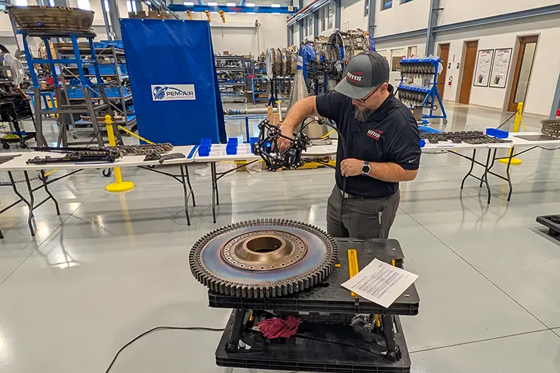
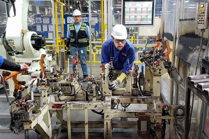
Yes. Our portable metrology equipment allows many inspections to be performed at the customer’s facility. On-site inspection is often the best option for large components, installed equipment, tooling, fixtures, assemblies, or parts that would be difficult or expensive to transport.
Shop-floor work is supported by dynamic referencing, which locks the scanner’s coordinate system to optical targets on the part so that vibration or movement mid-scan does not corrupt the data. We review the working area, access, environmental conditions, required accuracy, and safety requirements before scheduling the work.
13Can you inspect flexible, soft, or delicate parts?
In many cases, yes. Contact probes can deflect or deform rubber seals, foam, thin sheet metal, or silicone gaskets during measurement. Because optical 3D scanning is non-contact, it captures the part in its natural state without that risk.
Flexible parts still need to be supported in a controlled and repeatable condition. The inspection plan should define whether the part is measured in a free state, restrained state, assembled condition, or fixture. Without consistent support, the shape may change between measurements.
14Can 3D scanning inspect internal dimensions and hidden features?
Optical 3D scanners are limited to line-of-sight surface capture. They cannot measure enclosed chambers, internal threads, or blind internal channels without sectioning the part. For non-destructive internal inspection, industrial CT scanning captures internal and external geometry at the same time and can be compared to CAD in the same way.
15How does dimensional inspection support root cause analysis and process control?
When production parts fail assembly tests or show unexpected wear, overlaying a scanned part against its CAD model immediately reveals warp patterns, die wear, thermal shrinkage, or tool deflection that single-point measurements would miss.
Scanning parts at intervals across a production run also lets the software track dimensional shifts over time. Engineers can detect tool wear, mold degradation, or process drift early and schedule corrective maintenance before out-of-tolerance parts are produced.
16What is included in a dimensional inspection report?
The contents depend on the project, but a report may include overall color deviation maps, individual dimensional results with nominal and measured values, plus and minus deviations, pass-or-fail results, GD&T evaluations, datum and alignment information, cross-sectional comparisons, feature-location results, surface profile analysis, annotated screenshots, and inspection notes.
Reports are typically delivered as a PDF. Inspection project files and other data may also be available when requested in advance.
17What information do you need to quote a dimensional inspection project?
Please provide as much of the following as possible:
- A 3D CAD model and a dimensioned engineering drawing
- The required tolerances and the dimensions or features that must be inspected
- The required alignment or datum structure
- Overall part dimensions, weight, material, and surface finish
- Photographs of the part and the number of parts to be inspected
- Required report format and any customer or industry reporting requirements
- Whether the inspection will be performed at EMS3D or on-site
- Required completion date
It also helps to explain why the part is being inspected. A first article, a production problem, a tooling correction, incoming inspection, and an assembly-fit investigation may each call for a different inspection approach.
